In the first part of this series, I defined the voltage detector and monitor/reset IC and explained the different output types and some basic equipment. As the design becomes more complex, more advanced equipment may be required to successfully monitor the voltage. In this issue, I will focus on the various features of voltage detectors and supervisor/reset ICs to help designers choose the right circuit.
Programmable output delay
Unlike voltage detectors, voltage monitors typically use external capacitors with programmable output delays, making them extremely flexible. They can be used to properly sequence multiple power supplies in Field Programmable Gate Array (FPGA) applications or prevent system failures. When the supply voltage rises above the voltage threshold (plus hysteresis, if applicable), this normally triggers the device to "un-tag" the reset signal and return the system from the reset state. However, due to the delay caused by the delay capacitor (CD), the voltage must remain above the voltage threshold and the delay of the specified time delay before the reset signal cancels the flag. This prevents the system from returning prematurely from a reset state.
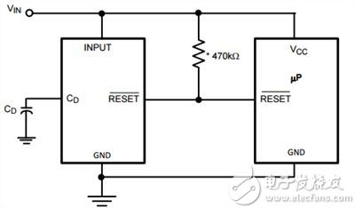
The programmable output delay is sometimes referred to as the programmable reset timeout period. Ceramic chip capacitors connected directly to the delay pin (sometimes referred to as CD or SRT) are usually sufficient to achieve a stable, well-defined output delay. As shown in Figure 1, the LM8365 has a programmable output delay.

Figure 1: LM8365 Typical Application Circuit with Programmable Output Delay
When the input voltage drops below the reset threshold, the reset pin goes low. When the input voltage rises above the threshold, there is a delay before the reset pin recovers. By increasing the capacitor (CD), the delay increases.
Manual reset
For a specific duration (usually microseconds), the manual reset input forces a reset when the manual reset (MR) pin is below the manual reset threshold (VMRT). As long as the MR pin is held low, the reset pin will remain active. After MR is higher than VMRT, this pin is released after the reset timeout period expires. This feature is very useful for microprocessor applications when users need to reset. It can also be used in applications that require a reset when a low voltage below the mains voltage is detected. A manual reset can completely control the reset instead of triggering only the low supply voltage.
Power failure input
Some voltage detectors and supervisor/reset ICs additionally enter power failure warnings to monitor power supplies other than the main power supply. This additional input is useful in systems that want to detect if a power supply has failed before an actual failure occurs. The threshold can vary with different devices, but the typical threshold is 1.225V for the internal reference voltage. If the power-fail input (PFI) pin is below the power-fail voltage threshold (VPFT), the power-fail output (PFO) decreases.
Typically, driven by a voltage divider connected to the main power supply, the power failure comparator indicates that the power supply is continuously dropping. Before the main supply voltage drops below the reset threshold, the PFI voltage is below the VPFT for a few milliseconds and it will issue an undervoltage warning in advance. The PFI pin can also be connected to the MR pin to force a low output signal for the voltage detector or a reset for the supervisor/reset IC.
Watchdog timer
A voltage detector with a watchdog timer and a monitor/reset IC wait for signal activity on the watchdog input (WDI) pin. If the monitor does not detect a signal in the watchdog window, reset the trigger. You can use an external capacitor to program this window to make the watchdog window more flexible.
Watchdog timers are often used for safety-critical applications or processor monitoring. If the microprocessor is not active for a certain duration, it needs to be reset. If the microprocessor does not work properly, this feature prevents the system from continuing to operate.
Low-voltage line output
When the power supply voltage drops below the reset threshold, the initial power failure warning light goes low. The indicator trigger is approximately 2% above the reset threshold to indicate low power and does not cause a reset.
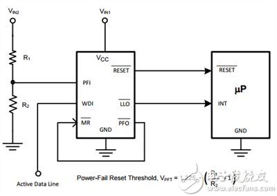
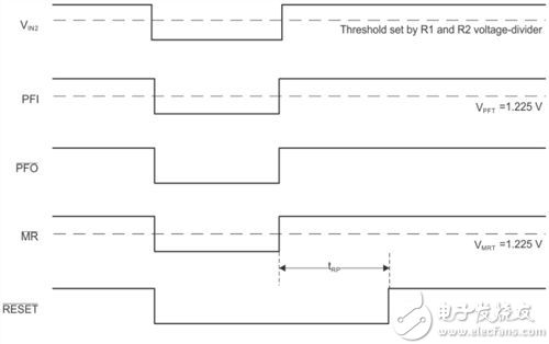
Figure 3 shows an example application circuit for the LM3710 ; Figure 4 shows an example timing diagram that contains an example of the functions I have discussed so far.

Figure 3: LM3710 Application Circuit
In addition to the standard reset, the LM3710 also features manual reset, power-fail input, watchdog timer, and low-level output, making it an extremely flexible device for many applications. The application circuit shown in Figure 3 above uses R1 and R2 as voltage dividers connected to VIN2 to set a power-fail reset threshold to monitor the second power supply. If the second supply voltage falls below the power-fail reset threshold, the PFI pin will be low, so the PFO pin will also fall low. Because this pin is connected to the MR pin, a reset will trigger.
A reset also occurs if no activity is detected in the watchdog window on the WDI pin. The WDI pin can be connected to the microprocessor and the microprocessor can send intermittent pulses to detect if it is still working. If the power supply voltage of VCC falls within about 2% of the reset voltage threshold, the low voltage line output (LLO) pin goes low. For example, the LLO pin can be connected to the microprocessor for detection. When the LLO pin becomes active, the signal sent to the microprocessor can cause some other action, such as sending a signal to another device or the LED blinking or giving the user some other alarm.

Figure 4: Example timing diagram for power failure and manual reset of the LM3710
The timing diagram in Figure 4 shows an example of monitoring the second voltage input (VIN2). When VIN2 connected to the PFI pin goes low, the PFO pin drops to a low level, causing the MR pin to fall to a low level and then triggering a reset. There are several ways to use power failure and manual reset, so it is up to you to determine your application requirements.
After reading Parts 1 and 2 of this blog series, you should understand the subtle differences between voltage detectors and voltage supervisor/reset ICs and the various functions available. There are countless applications that need to detect a supply voltage that exceeds a set voltage threshold, and the designer decides what will happen next. For example, do you want the system to flash or turn on the speaker or turn off other devices in the circuit when the battery is running low? Do you want users to be able to press the button to trigger the same conditions or other conditions? Do you want to monitor multiple voltages at different thresholds? When selecting a voltage detector or monitor/reset IC, first determine what you want to do and what functions are required, then determine the required equipment according to a specific specification, package, cost, etc. To view all voltage detectors and supervisor/reset ICs provided by Texas Instruments
Car cable harness, also known as a wire harness, cable assembly, wiring assembly or wiring loom, is an assembly of electrical cables or wires which transmit signals or electrical power. The cables are bound together by connector, terminal, cable ties, sleeves, electrical tape, conduit, PVC tube, corrugate tube, string, or a combination thereof.
Commonly used in automobiles, as well as construction machinery, cable harnesses provide several advantages over loose wires and cables. For example, many aircraft, automobiles and spacecraft contain many masses of wires which would stretch over several kilometres if fully extended. By binding the many wires and cables into a cable harness, the wires and cables can be better secured against the adverse effects of vibrations, abrasions, and moisture.
Car Wire Harness,Wiring Harness,Car Electrical Wiring Harness,American Autowire Mustang Harness
Dongguan YAC Electric Co,. LTD. , https://www.yacentercns.com