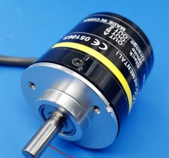
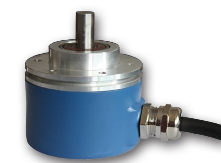
Photoelectric encoder:
The encoder is a kind of sensor. It is mainly used to detect the speed, position, angle, distance and counting of mechanical motion. Many motor controls need to be equipped with encoders for motor controllers as phase change, speed and position detection. The scope of application is quite extensive. According to the different ways of the encoder:
Incremental encoder
Absolute encoder
Hybrid encoder
1, incremental encoder
The incremental encoder corresponds to an incremental displacement for each output pulse signal, and it is capable of generating a pulse signal equivalent to the displacement increment. The incremental encoder measures the relative position increment relative to a certain reference point and cannot directly detect the absolute position information.
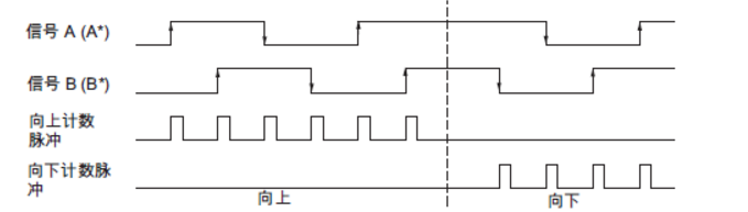
Incremental photoelectric encoder outputs A and B pulse signals with a phase difference of 90° (so-called two-phase quadrature output signals). According to the positional relationship between the two phases of A and B, the encoder can be easily judged. The direction of rotation. In addition, the code wheel generally provides an N-phase flag (indication) pulse signal for use as a reference zero, and a zero mark signal is issued every one rotation of the code wheel.
2, absolute encoder
Absolute encoders use different numbers to indicate each different incremental position. It is a sensor that directly outputs digital quantities.
The absolute encoder can read a fixed digital code corresponding to the position at any position of the rotary shaft, that is, directly read out the absolute value of the angular coordinate. In addition, there is no cumulative error in the absolute encoder relative to the incremental encoder, and the position information is not lost when the power is removed.
3, signal output
The signal output of the incremental photoelectric encoder is:
A open collector output
B voltage output
C line drive output
D push-pull output
3.1 open collector output
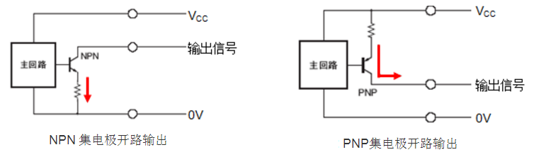
NPN open collector output: When logic 1, the output voltage is 0V;
PNP open collector output: When logic 1, the output voltage is the power supply voltage;
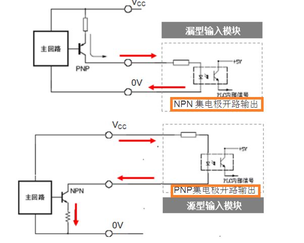
Wiring with PLC
3.2 Voltage output

The voltage output is based on the open collector output circuit. A pull-up resistor is connected between the power supply and the collector, so that a stable voltage state can be achieved between the collector and the power supply.
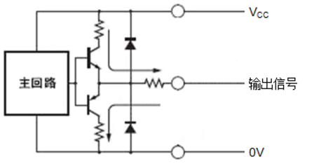
3.3 Push-pull output
The push-pull output mode consists of two transistors of PNP type and NPN type. When one of the transistors is turned on, the other transistor is turned off, and the two output transistors operate alternately.
This form of output has high input impedance and low output impedance, so it can also provide a wide range of power supplies at low impedance. Since the input and output signals have the same phase and wide frequency range, they are also suitable for long-distance transmission. The push-pull output circuit can be directly connected to the NPN and PNP open-collector input circuits, ie, to modules with source or sink inputs.
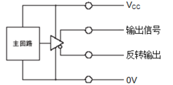
3.4 line drive output
The line drive output interface uses a dedicated IC chip, the output signal conforms to the RS-422 standard, and is output in differential form. Therefore, the line drive output signal has stronger anti-interference ability and can be applied to high-speed and long-distance data transmission occasions. It has the characteristics of fast response and strong anti-noise performance.
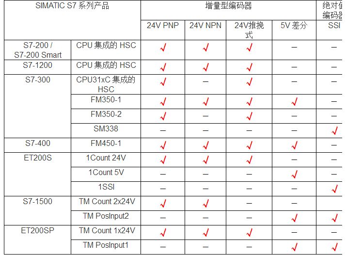
4, Siemens PLC and encoder compatibility
5, matters needing attention
5.1 Encoder type: Incremental encoder or absolute encoder.
5.2 Output signal type: Determine the output interface type (NPN, PNP) for incremental coding.
5.3 Signal voltage level: Confirm the voltage level of the signal (DC24V, DC5V, etc.).
5.4 Maximum output frequency: Confirm the maximum output frequency and resolution, number of bits and other parameters.
6, judge the quality of the encoder
6.1 NPN encoder: measure the voltage between the positive pole of the power supply and the signal output line with a multimeter
· The output voltage is close to the supply voltage when turned on
· The output voltage is close to 0V when turned off
6.2 PNP encoder: measure the voltage between the negative pole of the power supply and the signal output line with a multimeter.
· The output voltage is close to the supply voltage when turned on
· The output voltage is close to 0V when turned off
7, four times the frequency
For incremental signals, multiple evaluation modes can be configured, including dual evaluation and quad evaluation. The quadruple evaluation means that the positive and negative edges of the signals A and B are judged at the same time, and the count value is obtained. For the quadruple evaluation mode, because one pulse is processed four times (four evaluations), Therefore, the count value read is four times the actual number of input pulses, and the resolution of the measurement can be improved by multiple evaluation of the signal.
Outdoor low power LED lamps,Aluminum Alloy LED lamps,LED point light
Kindwin Technology (H.K.) Limited , https://www.ktl-led.com