1, incoming line
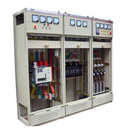
The incoming mode is determined by the current flowing into the inlet of the power distribution cabinet, for example, flowing in from the top of the cabinet (this way generally leads to current through the busway), which is called advancement;
The incoming flow from the bottom of the cabinet is called the next step (this method generally uses a cable to draw current);
The incoming flow from the side of the cabinet is called side entry (this method is generally used when the incoming line cabinet and the transformer are next to each other, etc.)
2, the way out
As we can see above, the way of appearance is determined by the location of the current flowing out of the outlet of the power distribution cabinet, as above, but generally only the upper and lower lines.
3, the specific way of entering and leaving the line
Up and down, down and up, side in and out, side in and out, etc.
Simple summary:
1. If it is the busbar bridge incoming line, it must be on the incoming line. If it is a cable, it is better to use the lower incoming line.
2. The connection mode between the transformer and the low-voltage incoming line cabinet mainly includes: the copper row side incoming line, the bus line bridge cabinet top incoming line and the cabinet bottom cable incoming line.
3, the cable is generally down and down, the bus into and out more, depending on the designer's considerations, including equipment selection, wiring, civil conditions, investment and the owner's taste and so on.
In addition to considering the convenience of construction, there are two other factors to consider:
First, we must consider the magnitude of the current on the low-voltage side. If the current is too large and it is pushed in and out through the cable, several cables must be put together, which does not meet the economic operating conditions.
Second, consider the economic benefits of the investor, if the current allows the cable or busbar to enter the line, it is necessary to consider the cost. In general, the cost of incoming lines on the bridge is high. (From the user's consideration, of course, the more economically the better, from the contractor to consider the more expensive the better!)
In short:
According to the actual situation, there is no uniform regulation. Generally speaking, if the capacity is small, the cable is often used, and the lower entry line is convenient. Larger capacity often uses more busbars or dense busbars, so the upper feeder is more convenient.

First, the incoming cabinet
In layman's terms, the incoming cabinet is a switchgear that introduces power from the outside. Generally, a 10kV power supply is introduced from the power supply network, and the 10kV power supply is sent to the 10kV bus through the switchgear, and the switchgear used for guiding and sending is the incoming cabinet.
Specifically, the incoming line cabinet is introduced into the main switchgear of the power distribution unit by a low voltage power supply (low voltage side of the transformer). For substations of voltage levels of 35-110kV and above, the incoming line cabinets are transformer low-voltage (10kV) switchgear. That is, the first cabinet connected to the initial end of the 10kV busbar from the low-voltage side of the transformer is called the incoming cabinet, also known as the low-incoming cabinet.
The function of the incoming line cabinet: the incoming line cabinet is the main switchgear on the load side. The cabinet is responsible for the current carried by the whole section of the busbar. Since the switchgear is connected with the main transformer and the low-voltage side load output, it is important to play its role. Where. In the case of relay protection, when the main transformer low-voltage side busbar or circuit breaker fails, it is necessary to rely on the overcurrent protection of the low-voltage side of the transformer to trip the inlet cabinet switch to remove the fault. The low-voltage side busbar fault must also be cut off by the backup protection on the low-voltage side of the main transformer. The transformer differential protection action also removes the transformer low-voltage side circuit breaker, that is, the incoming line cabinet.
Second, the outlet cabinet
The outlet cabinet is the switchgear that distributes electrical energy from the busbar. From the 10kV busbar to the power transformer via the switchgear, this switchgear is one of the 10kV outlet cabinets. Install the outlet switch cabinet on the low voltage side of the transformer, send the electric energy to the low voltage bus through the switch cabinet, and then install several low voltage switch cabinets on the low voltage side to send the power to each power station. These low voltage switchgear cabinets are all outlet cabinets.
If a low-voltage system is introduced from the nearest place, the low-voltage switchgear that is connected to the incoming line is also an incoming line cabinet, just a low voltage. The switchgear that is led out from the low voltage busbar is also the outlet cabinet.
In some cases, the outlet cabinet is also called the feeder cabinet. In fact, it is just a different name.
The above two types of switchgear are distinguished according to their functions, and are used in both low voltage and high voltage, and the same type of switchgear (such as low pressure GGD, high pressure KNY28) can be used as inlet cabinets, outlet cabinets or Feeder cabinet.
Incoming cabinet power failure operation procedure
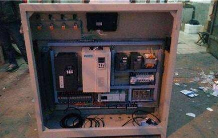
1) Operate the instrument on the door to close and switch the switch to make the circuit breaker open and power off. At the same time, the red closing indicator on the instrument door is off, the green opening indicator is on, check other related signals, everything is normal, and the power failure is successful. (When operating the combination switch, turn the operation handle counterclockwise to the panel indication position. After releasing the hand, the operation handle should be automatically reset to the pre-position position.)
2) Insert the handle of the circuit breaker handle into the handle of the handle and press it down firmly. Turn the handle counterclockwise for about 20 turns. Remove the handle when the handle is obviously blocked and accompanied by a “click†sound. The car is in the test position, the aviation plug is unlocked, the door of the handcart is opened, and the air is inserted manually. (The handcart main circuit is disconnected)
3) Push the transfer car and lock it, pull out the circuit breaker handcart to the transfer car, and remove the transfer car. (When pulling the circuit breaker, press the two push-pull handles of the circuit breaker to the middle, and pull back with force (to pull out the cabinet). After the circuit breaker is pulled to the transfer trolley and in place, release the push-pull handle and the handle should be automatically reset.)
4) Observe the live display and confirm that it can be operated without power.
5) Insert the grounding switch operating handle into the hexagonal hole on the lower right side of the middle door, rotate clockwise to make the grounding switch in the closing position, confirm that the grounding switch is already closed, open the lower door of the cabinet, and the maintenance personnel can enter the maintenance and overhaul. .
6) The grounding switch and the circuit breaker and the cabinet door are interlocked. Only when the circuit breaker is in the test position or outside the cabinet, the grounding switch can be combined. Only after the grounding switch is opened can the circuit breaker be shaken from the test position. To the working position, it is not allowed to operate. The grounding switch and the cabinet door interlock can be unlocked urgently. It can be unlocked urgently only when necessary, otherwise there is danger of electric shock.
Power outage operation procedure of the outlet cabinet
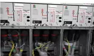
1) Close all doors and rear sealing plates and lock them. (The grounding switch can be closed when the door is closed)
2) Insert the grounding switch operating handle into the hexagonal hole on the lower right side of the middle door, rotate it counterclockwise, so that the grounding switch is in the opening position, take out the operating handle, and the interlocking plate automatically bounces back at the operating hole to cover the operating hole. The door is locked.
3) Push the transfer trolley and position it, push the circuit breaker handcart into the cabinet and position it in the test position. (When pushing the circuit breaker, press the two push-pull handles of the circuit breaker to the middle, and push forward with force ( Push inside the cabinet. After the circuit breaker reaches the test position, release the push-pull handle and the handle should be automatically reset.) Manually insert the aviation plug, close the handrail door and lock it.
4) Observe whether the instruments and signals of the upper cabinet door are normal. (In normal time, the integrated relay power light is on, the hand test position light, the circuit breaker opening indicator and the energy storage indicator are on. If all the indicators are off, open the upper door to confirm whether the bus power switch is closed. If the indicators are still off, the control loop needs to be repaired.)
5) Insert the handle of the circuit breaker handle into the handle of the crank handle and press it down firmly. Turn the handle clockwise clockwise for about 20 turns. When the handle is obviously blocked and accompanied by a “click†sound, remove the handle. The car is in the working position, the aviation plug is locked, and the main circuit of the circuit breaker is connected to view the relevant signals. (At this time, the working position of the handcart is on, and the test position of the handcart is off.)
6) Operate the switch on the door of the instrument to make the circuit breaker close and send power. At the same time, the red closing indicator on the instrument door is on, the green opening indicator is off, check the live display and other related signals, everything is normal, and the power is successfully delivered. . (When operating the combination switch, turn the operation handle clockwise to the panel indication position. After releasing the hand, the operation handle should be automatically reset to the pre-close position.)
7) If the circuit breaker is automatically opened after the switch is closed or the motor is automatically opened during operation, it is necessary to judge which fault is eliminated and then re-send the power according to the above procedure. (When the line fault circuit breaker is opened, an audible and visual alarm will be issued, that is, the panel red fault indicator will be on, and the fault sound will sound. At this time, the integrated relay will be observed, such as the TRIP light, and any IL1, IL2, IL3 lights will be on. Or at the same time, the fault is the overcurrent of the line. If the TRIP light is on and the IRF light is on, the fault is a comprehensive relay abnormality. If the TRIP light is on, and the IO light is on, it is the ground fault of the line. After the repair is completed, it needs to be comprehensively protected. The panel RESET/STEP button manually resets the integrated relay. If the panel signal relay is off, it is the transformer over-temperature fault, indicating that the transformer is faulty or heavily overloaded. After the fault is removed, the signal relay must be manually reset to re-close.
Rotary encoders are used as sensors for angle,position,speed and acceleration. We can offer incremental encoders and absolute encoders.
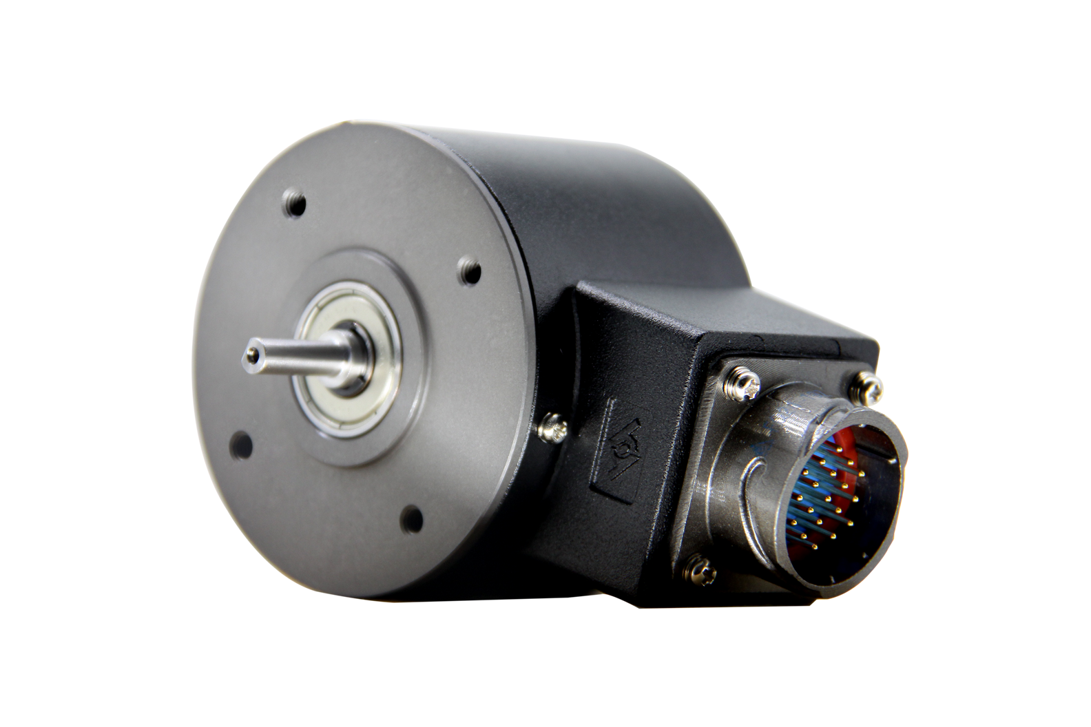
Absolute Encoder,Custom Encoder On Motor,Custom Optical Encoders,High Resolution Encoder
Yuheng Optics Co., Ltd.(Changchun) , https://www.yhencoder.com